Tuesday, August 7, 2018

IOS DEVELOPMENT


Image result for ios development logo
   

 DEVELOPMENT


iOS (iPhone, iPad) 


iOS is a mobile operating system developed and distributed by Apple Inc. It was originally released in 2007 for the iPhone, iPod Touch, and Apple TV. iOS is derived from OS X, with which it shares the Darwin foundation. iOS is Apple's mobile version of the OS X operating system used in Apple computers.
Image result for ios developer images


 INTRODUCTION

iOS, which was previously called iPhone OS, is a mobile operating system developed by Apple Inc. Its first release was in 2007, which included iPhone and iPod Touch. iPad (1st Generation) was released in April 2010 and iPad Mini was released in November 2012. The iOS devices get evolved quite frequently and from experience, we find that at least one version of iPhone and iPad is launched every year. Now, we have iphone5 launched which has its predecessors starting from iPhone, iPhone 3gs, iPhone 4, iPhone 4s. Similarly, iPad has evolved from iPad (1st Generation) to iPad (4th Generation) and an additional iPad Mini version. The iOS SDK has evolved from 1.0 to 6.0. iOS 6.0, the latest SDK is the only officially supported version in Xcode 4.5 and higher. We have a rich Apple documentation and we can find which methods and libraries can be used based on our deployment target. In the current version of Xcode, we’ll be able to choose between deployment targets of iOS 4.3, 5.0 and 6.0. The power of iOS can be felt with some of the following features provided as a part of the device. 

 Maps 
 Siri 
 Facebook and Twitter 
 Multi-Touch  Accelerometer 
 GPS 
 High end processor 
 Camera 
 Safari 
 Powerful APIs 
 Game center 
 In-App Purchase 
 Reminders
  Wide Range of gestures 

The number of users using iPhone/iPad has increased a great deal. This creates the opportunity for developers to make money by creating applications for iPhone and iPad the Apple's App Store.

Registering as an Apple Developer


An Apple ID is most necessary if you are having any Apple device and being a developer, you definitely need it. It's free and hence, no issues in having one. The benefits of having an Apple account are as follows:

      Access to development tools. 
      Worldwide Developers Conference (WWDC) videos. 
      Can join iOS developer program teams when invited. 


To register an Apple account, follow the steps given below: 
1. Click the link (https://developer.apple.com/programs/register/) and select "Create Apple ID".

2. Provide the necessary information, which is self explanatory as given in the page. 

3. Verify your account with your email verification and the account becomes active.

4. Now you will be able to download the developer tools like Xcode, which is packaged with iOS simulator and iOS SDK, and other developer resources.

iOS –Xcode Installation

1.Download the latest version of Xcode from (https://developer.apple.com/downloads/)


2. Double click the Xcode dmg file. 

3. You will find a device mounted and opened.

4. There will be two items in the window that's displayed namely, Xcode application and the Application folder's shortcut.

 5. Drag the Xcode to application and it will be copied to your applications. 

6. Now Xcode will be available as a part of other applications from which you can select and run. You also have another option of downloading Xcode from the Mac App store and then install following the step-by-step procedure given on the screen.


iOS ─ First iPhone Application


Now we are going to create a simple single view application(a blank app) that will run on the iOS simulator. 
The steps are as follows. 

1. Open Xcode and select Create a new Xcode project.


2. Select Single View Application.


3. Enter the product name, i.e., the name of the application, organization name, and then the company identifier.


4. Ensure that Use Automatic Reference Counting is selected in order to automatically release the resources allocated once it goes out of scope. Click Next.


5. Select the directory for the project and select create.


6. You will see a screen as follows: 


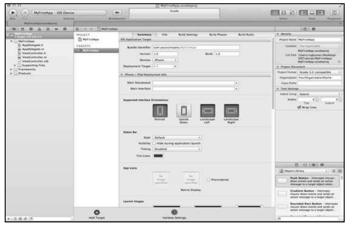
In the screen above, you will be able to select the supported orientations, build and release settings. There is a field deployment target, the device version from which we want to support, lets select 4.3, which is the minimum deployment target allowed now. For now, these are not required and let's focus on running the application.

7. Now, select iPhone simulator in the drop down near Run button and select run


8. That's it; you have successfully run your first application. You will get an output as follows

Now let's change the background color, just to have a start with the interface builder. Select ViewController.xib. Select background option in the right side, change the color and run.


If anyone is interested for doing Research in above subject for BTech/MTech/PHD Engineering project work
Kindly Contact Below

Contact Details:
Santosh Gore Sir
Ph:09096813348 / 8446081043 / 0253-6644344
Email: sai.info2009@gmail.com 


Monday, August 6, 2018

Android Development

ANDROID

Sai Info solution provide the Project Development & Training. We Develop Project for BE/ME/PHD.Android is an open source and Linux-based Operating System for mobile devices such as smartphone and tablet computers. Android was developed by the Open Handset Alliance, led by Google, and other companies.Android offers a unified approach to application development for mobile devices which means developers need only develop for Android, and their applications should be able to run on different devices powered by Android.The first beta version of the Android Software Development Kit (SDK) was released by Google in 2007 where as the first commercial version, Android 1.0, was released in September 2008.On June 27, 2012, at the Google I/O conference, Google announced the next Android version, 9.0 pie.  

Why Android ?


Features of Android

Android is a powerful operating system competing with Apple 4GS and supports great features. Few of them are listed below −

1
Beautiful UI
Android OS basic screen provides a beautiful and intuitive user interface.
2
Connectivity
GSM/EDGE, IDEN, CDMA, EV-DO, UMTS, Bluetooth, Wi-Fi, LTE, NFC and WiMAX.
3
Storage
SQLite, a lightweight relational database, is used for data storage purposes.
4
Media support
H.263, H.264, MPEG-4 SP, AMR, AMR-WB, AAC, HE-AAC, AAC 5.1, MP3, MIDI, Ogg Vorbis, WAV, JPEG, PNG, GIF, and BMP.
5
Messaging
SMS and MMS
6
Web browser
Based on the open-source WebKit layout engine, coupled with Chrome's V8 JavaScript engine supporting HTML5 and CSS3.
7
Multi-touch
Android has native support for multi-touch which was initially made available in handsets such as the HTC Hero.
8
Multi-tasking
User can jump from one task to another and same time various application can run simultaneously.
9
Resizable widgets
Widgets are resizable, so users can expand them to show more content or shrink them to save space.

Android Applications

Android applications are usually developed in the Java language using the Android Software Development Kit.Once developed, Android applications can be packaged easily and sold out either through a store such as Google PlaySlideMEOpera Mobile StoreMobangoF-droid and the Amazon Appstore.Android powers hundreds of millions of mobile devices in more than 190 countries around the world. It's the largest installed base of any mobile platform and growing fast. Every day more than 1 million new Android devices are activated worldwide.

Categories of Android applications

There are many android applications in the market.The top categories are:-

History of Android

The code names of android ranges from A to N currently, such as Aestro, Blender, Cupcake, Donut, Eclair, Froyo, Gingerbread, Honeycomb, Ice Cream Sandwitch, Jelly Bean, KitKat, Lollipop and Marshmallow. Let's understand the android history in a sequence.


If anyone is interested for doing Research in above subject for BTech/MTech/PHD Engineering project work
Kindly Contact Below

Contact Details:
Santosh Gore Sir
Ph:09096813348 / 8446081043 / 0253-6644344
Email: sai.info2009@gmail.com 


Saturday, August 4, 2018

HADOOP

Sai Info solution provide the Project Development & Training. We Develop Project for BE/ME/PHD. Hadoop is an open-source framework that allows to store and process big data in a distributed environment across clusters of computers using simple programming models. It is designed to scale up from single servers to thousands of machines, each offering local computation and storage. This brief tutorial provides a quick introduction to Big Data, MapReduce algorithm, and Hadoop Distributed File System.Hadoop is an Apache open source framework written in java that allows distributed processing of large datasets across clusters of computers using simple programming models. A Hadoop frame-worked application works in an environment that provides distributed storage and computation across clusters of computers. Hadoop is designed to scale up from single server to thousands of machines, each offering local computation and storage. Due to the advent of new technologies, devices, and communication means like social networking sites, the amount of data produced by mankind is growing rapidly every year. The amount of data produced by us from the beginning of time till 2003 was 5 billion gigabytes. If you pile up the data in the form of disks it may fill an entire football field. The same amount was created in every two days in 2011, and in every ten minutes in 2013. This rate is still growing enormously. Though all this information produced is meaningful and can be useful when processed, it is being neglected.

What is Big Data?

Big data means really a big data, it is a collection of large datasets that cannot beprocessed using traditional computing techniques. Big data is not merely a data, rather it has become a complete subject,which involves various tools, technqiues and frameworks.

EXAMPLE

3-D Face Image identification from video streaming using Map Reduce


 ABSTRACT

massive face dentification system recognize a face from a lot of  faces at public places. There are two of techniques are used to  hit the goal: one is the 3Dface identification technique and the  other is the Hadoop detection technique. Face identification  technique find a similar face by 3D face features form mass  face data. The Hadoop is a parallel processing structure; it can  boost the computation ability. From imulation outcome, it is  demonstrate that our algorithm is an efficient  and accurate method for huge face identification.

Fig. 1 Object extraction and matching with the resultant image. 


Fig. 2 Shows Massive face identification structure in 
Hadoop.


INTRODUCTION

 Face identification is important task for several applications  on human being life. There are some examine was published  and described it below. I detect faces by using a hierarchical  knowledge-based method. I use three level resolutions in  their algorithm. The coarse-to-fine strategy reduce the computation is an advantage in this method. I also use local feature detector and random graph matching techniques to create a probabilistic method can locate a face  in a scene. By using five features like two eyes, two nostril,  and Nose/lip junction to depict a typical face. I am trying to define a facial template and relative distances of any pair  official features. This method can detect the testing object is  a human face or not. I will use a general and complete face detection technique. It  is a valuable method for face detection and surveying  detecting faces in images. For face image comparison, it is a hard work because it  needs a lot of working out and it cannot achieve 100%  accuracy. If I want to improve the comparison accuracy then  the multiple face indifferent angle can be  achieve the goal.  Furthermore ,if I want search a people from public places, it  is more difficult because it is related to real time operation  problems. It is a massive computation. However, the parallel processing technique increases computational capacity. For  a huge data, it needs massive computation ability. It needs  several computer works together to share the data. Therefore, Hadoop structure is a suitable system for solving the huge face identification difficulty.

What is Map Reduce?


MapReduce is a processing technique and a program model for distributed computing based on java. The MapReduce algorithm contains two important tasks, namely Map and Reduce. Map takes a set of data and converts it into another set of data, where individual elements are broken down into tuples (key/value pairs). Secondly, reduce task, which takes the output from a map as an input and combines those data tuples into a smaller set of tuples. As the sequence of the name MapReduce implies, the reduce task is always performed after the map job.
The major advantage of MapReduce is that it is easy to scale data processing over multiple computing nodes. Under the MapReduce model, the data processing primitives are called mappers and reducers. Decomposing a data processing application into mappers and reducers is sometimes nontrivial. But, once we write an application in the MapReduce form, scaling the application to run over hundreds, thousands, or even tens of thousands of machines in a cluster is merely a configuration change. This simple scalability is what has attracted many programmers to use the MapReduce model.


If anyone is interested for doing Research in above subject for BTech/MTech/PHD Engineering project work
Kindly Contact Below

Contact Details:
Santosh Gore Sir
Ph:09096813348 / 8446081043 / 0253-6644344
Email: sai.info2009@gmail.com 


ANTENNA


Sai Info solution provide the Project Development & Training. We Develop Project for BE/ME/PHDIn radio, an antenna is the interface between radio waves propagating through space and electric currents moving in metal conductors, used with a transmitter or receiver. In transmission, a radio transmitter supplies an electric current to the antenna's terminals, and the antenna radiates the energy from the current as electromagnetic waves (radio waves). In reception, an antenna intercepts some of the power of an electromagnetic wave in order to produce an electric current at its terminals, that is applied to a receiver to be amplified. Antennas are essential components of all radio equipment, and are used in radio broadcasting, broadcast television, two-way radio, communications receivers, radar, cell phones, satellite communications and other devices. An antenna is an array of conductors (elements), electrically connected to the receiver or transmitter. During transmission, the oscillating current applied to the antenna by a transmitter creates an oscillating electric field and magnetic field around the antenna elements. These time-varying fields radiate energy away from the antenna into space as a moving transverse electromagnetic field wave. Conversely, during reception, the oscillating electric and magnetic fields of an incoming radio wave exert force on the electrons in the antenna elements, causing them to move back and forth, creating oscillating currents in the antenna. Antennas can be designed to transmit and receive radio waves in all horizontal directions equally (omnidirectional antennas), or preferentially in a particular direction (directional or high gain antennas). An antenna may include parasitic elements, parabolic reflectors or horns, which serve to direct the radio waves into a beam or other desired radiation pattern. The first antennas were built in 1888 by German physicist Heinrich Hertz in his pioneering experiments to prove the existence of electromagnetic waves predicted by the theory of James Clerk Maxwell. Hertz placed dipole antennas at the focal point of parabolic reflectors for both transmitting and receiving.

Today will see one example  application of Antenna in  A Survey on Emerging WiMAX Antenna Technologies and Slotted Microstrip Patch Antenna’s for WiMAX Applications

A Survey on Emerging WiMAX Antenna Technologies and Slotted Micro strip Patch Antenna’s for WiMAX Applications


ABSTRACT


WiMax (Worldwide Interoperability for  Microwave access) has been established by the IEEE 802.16  working group. WiMax theoretically can have coverage of up  to  50 km radius. WiMax technology is replacement for wireless  internet access. WiMax has three allocated frequency bands.  The low band (2. 5-2.69 GHz), the middle band (3.2-3.8 GHz)  and the upper band (5.2-  5.8 GHz).New WiMax antenna  technologies like SISO,SIMO,MISO,MIMO,AAS  are  developed  which promises increased data rates, greater bandwidth,  security and more productive use of the wireless spectrum.  The  antenna is very essential element  of communication as it is  used for a transmitting and receiving electromagnetic waves.  Today Communication devices such as mobile phones become  very thin and smarter, support several applications and  require higher bandwidth where the microstrip antennas  are  the better choice compare to conventional antennas. This  paper presents a literature survey of slotted microstrip patch  antenna’s these are  Double C-slot MSA and C-slot  MSA  for  WiMAX applications. In this paper we also discussed the basics  of microstrip antennas with their advantage and  disadvantages.


Fig.-Structure of microstrip antenna

ANTENNA PARAMETERS


Performance  of the antenna s measured by different  parameter such as VSWR, Return Loss, Antenna Gain,  Directivity, Antenna Efficiency and Bandwidth is analyzed.

(a)  Gain: The gain of an antenna is defined as the ratio of the  intensity, in a given direction, to the radiation intensity that  would be obtained if the power accepted by the antenna were  radiated isotropically.

(b) Radiation Pattern:  The radiation pattern is defined as a  mathematical function or a graphical representation of the  radiation properties of the antenna as a function of space  coordinates.

(c) Antenna Efficiency: It is a ratio of total power radiated  by an antenna to the input power of an antenna.

(d)  Bandwidth:  Is is range of frequencies over which  antenna operates efficiently. Bandwidth is  difference  between upper cutoff frequency and lower cut off frequency.

(e)  VSWR: Voltage standing wave ratio is defined as  VSWR=Vmax/Vmin.It should lie between 1 and 2.

(f) Return loss: Return loss is the reflection of signal power  from the insertion of  a device in a transmission line. Hence  the RL is a parameter similar to the VSWR to indicate how  well the matching between the transmitter and antenna has taken place.


ADVANTAGES AND DISADVANTAGES


A.  Advantages-

           1.  Low weight
               2.  Low profile
               3.  Require no cavity Backing 
               4.  Linear & circular polarization
               5.  Capable of dual and triple frequency operation
               6.  Feed lines & matching network can be fabricated 
                   simultaneously

B.  Disadvantages-

           1.  Low efficiency
              2.  Low gain
              3.  Large ohmic losses in feed structure.
              4.  Low power handling capacity
              5.  Excitation of surface wave
              6.  Polarization purity is difficult to achieve.
              7.  Complex feed structure required high 
                   performance arrays. 

REFERENCE ARTICLES


If anyone is interested for doing Research in above subject for BTech/MTech/PHD Engineering project work
Kindly Contact Below

Contact Details:
Santosh Gore Sir
Ph:09096813348 / 8446081043 / 0253-6644344
Email: sai.info2009@gmail.com 


Wednesday, August 1, 2018

POWER SYSTEM


Sai Info solution provide the Project Development & Training.We Develop Project for BE/ME/PHD. An electric power system is a network of electrical components deployed to supply, transfer, and use electric power. An example of an electric power system is the grid that provides power to an extended area. An electrical grid power system can be broadly divided into the generators that supply the power, the transmission system that carries the power from the generating centers to the load centers, and the distribution system that feeds the power to nearby homes and industries. Smaller power systems are also found in industry, hospitals, commercial buildings and homes. The majority of these systems rely upon three-phase AC power—the standard for large-scale power transmission and distribution across the modern world. Specialized power systems that do not always rely upon three-phase AC power are found in aircraft, eletric rail systems, 


COMPONENTS OF POWER SYSTEM 

Supplies:


                      All power systems have one or more sources of power. For some power systems, the source of power is external to the system but for others it is part of the system itself—it is these internal power sources that are discussed in the remainder of this section. Direct current power can be supplied by batteriesfuel cells or photovoltaic cells. Alternating current power is typically supplied by a rotor that spins in a magnetic field in a device known as a turbo generator. There have been a wide range of techniques used to spin a turbine's rotor, from steam heated using fossil fuel(including coal, gas and oil) or nuclear energy, falling water (hydroelectric power) and wind (wind power).


Loads:

               
            Power systems deliver energy to loads that perform a function. These loads range from household appliances to industrial machinery. Most loads expect a certain voltage and, for alternating current devices, a certain frequency and number of phases. The appliances found in your home, for example, will typically be single-phase operating at 50 or 60 Hz with a voltage between 110 and 260 volts (depending on national standards). An exception exists for centralized air conditioning systems as these are now typically three-phase because this allows them to operate more efficiently. All devices in your house will also have a wattage, this specifies the amount of power the device consumes. At any one time, the net amount of power consumed by the loads on a power system must equal the net amount of power produced by the supplies less the power lost in transmission


Conductors:


                          Conductors carry power from the generators to the load. In a grid, conductors may be classified as belonging to the transmission system, which carries large amounts of power at high voltages (typically more than 69 kV) from the generating centres to the load centres, or the distribution system, which feeds smaller amounts of power at lower voltages (typically less than 69 kV) from the load centres to nearby homes and industry.


ABSTRACT

the design, implementation, and experimental validation of a method for fault prognosis for power electronics systems using an adaptive parameter identification approach. The adaptive parameter identifier uses a generalized gradient descent algorithm to compute real-time  estimates of system parameters (e.g. capacitance, inductance, parasitic resistance) in arbitrary switching power electronics systems. These estimates can be used to monitor the overall health of a power electronics system, and predict when faults are more likely to occur. Moreover, the estimates can be used to tune control loops that rely on the system parameter values. The parameter identification algorithm is general in that it can be applied to a broad class of systems based on switching power converters. We present a real-time experimental validation of the proposed fault prognosis method on a 3 kW solar photovoltaic interleaved boost dc-dc converter system for tracking changes in passive component values. The proposed fault prognosis method enables a flexible and scalable solution for condition monitoring and fault prediction in power electronics systems


INTRODUCTION

Many mission-critical power electronics systems, including renewable energy integration, data center power delivery, and motor drives applications, require high reliability and availability of service. In many of these scenarios, techniques for fault prognosis are commonly employed, that is, methods for actively monitoring the system condition and predicting when failures or faults will occur. A central technology that enables fault prognosis is parameter identification, or identify-ing the values of system parameters in a real-time and online manner. By tracking the values of important system parameters in real-time, operators can actively monitor the overall health of a system and anticipate when maintenance or repairs will be needed. Moreover, fault prognosis can be achieved by monitoring if estimated parameter values are above or below an accepted tolerance range. The failure modes and mechanisms for power electronics systems have been widely investigated, for instance in. Passive components, such as capacitors and inductors, are a key failure point. Table I provides an overview of the common failure modes of passive components in a power electronics systems and the effect that these failures have on the resulting parameter value and ESR. The reasons for these failures vary widely, and include manufacturing defects, harsh environmental conditions (e.g. temperature and humidity), aging, high voltage stress, insulation failures, interconnection failures, mechanical wear, and vibrations and shocks. Moreover, the effect of the failures can be classified as either ‘hard’ or ‘soft’ faults. A hard fault is one that causes a sudden and catastrophic effect in the system (e.g. a short circuit), while a soft fault is one that causes a gradual effect or degradation in the system, generally related to lifetime wear or aging. Parameter identification has been investigated previously in the context of power electronics systems. One salient application for parameter identification in power electronics systems has been for estimating the capacitance or equivalent series resistance (ESR) of a dc-link capacitor. In many converters, the dc-link capacitor, particularly electrolytic capacitors, is one of the primary points of failure in the converter. Actively monitoring the capacitance or ESR of the capacitor enables detection and prediction of when these failures will occur.


If anyone is interested for doing Research in above subject for BTech/MTech/PHD Engineering project work
Kindly Contact Below

Contact Details:
Santosh Gore Sir
Ph:09096813348 / 8446081043 / 0253-6644344
Email: sai.info2009@gmail.com 


Sensor ventilator for COVID-19 The COVID-19 virus is spread by direct contact with an infected person's respiratory droplets (generated ...